Hardware Schematic
One of the prime considerations in the choice of the hardware components was the ease of construction. The easiest, and
possibly the cheapest, solution would have been to use surface mount components for the PIC and the USB connectivity.
However, not many 'amateurs' are happy with soldering SMD components and therefore I decided that the design had to be
based around 'through hole' technology. I had already decided that I wanted to use an FTDI FT245 USB FIFO chip as it was
capable of providing a 300kbytes per second transfer rate when used with the royalty free drivers provided by FTDI. The
down side to this was that the FTDI chip only comes in SMD format so an alternative solution was required. I then discovered
that a couple of companies were producing daughter boards containing the SMD FTDI chip and associated components with standard
24 by 0.6" and 32 by 0.6" " DIL plug-in connectivity. I decided to use a product made by DLP (www.dlpdesign.com/usb/) that utilise's
a 24 pin DIP that would plug into a standard 0.6" wide 24 pin socket.
In choosing the appropriate PIC it was a trade off between the number of port pins required together with the code space
needed to implement the design. I chose a 16F873 which has 3 more ports that the design requires together with 4Kbytes of code
space (currently about 1400 bytes free).
The schematic below provides the wiring details. I have not bothered to produce a PCB for the design I have used a small piece
of stripboard as the wiring required is relatively simple and should not present a user with soldering experience with too many
problems. The connection for the LCD module is made from SIP pins and mates with SIP sockets soldered to the LCD display PCB.
It must be recognised that the existing design is intended for the standard(?) 14/16 pin in-line connectors and if an LCD module
containing two rows of 7/8 pins is used the layout will have to be changed. It is VITAL that users ensure that the LCD module
they intend to use has the pins organised out as shown in the diagram below. If mistakes are made in the wiring of this part of the
interface the probable result will be the destruction of the LCD display module.
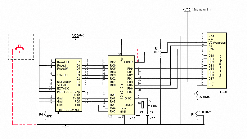
The red dotted connection shows how a reset button can be connected if the user requres this feature. Construction of the
project is very simple. I have made sockets for the USB Module and the PIC from turned pin SIL socket strips as these provide a
reliable and inexpensive method, but if the user so desires, standard IC sockets can be used. As can be seen in the picture
below only 7 additional components are required and the detailed component list is also shown. Also shown are the suppliers
from whom I obtained the components together with that supplier's part number. I am sure that all components other than the USB
module can be obtained from a variety of suppliers, most likely from your currently favoured company.
The value of R2 should be chosen to meet the maximum current requirement of the LED backligh fitted to the LCD module used.
The 22ohm value used should be OK for most modules but could result in a lower intensity than some users might require.
Note 1: The maximum current that can be sourced from the USB +5v supply (using this design) is 100Ma. The interface requires
a maximum of around 40Ma leaving 60Ma for driving the LCD logic and backlight. As the logic requirement is normally less than 5Ma
it means that for all practcal puposes it can be ignored. In my test system, with the 22ohm resistor and 100ohm variable shown, the
backlight cuurent was about 45Ma and so it was safe to link the V(5V) and VCC(5V) points together, but using other LCD modules that might
not be the case. Users must ensure that an appropriate resistor is used to limit the backlight current to less than 55 - 60Ma if these
points are to be linked. If the display requires more than 60Ma then an 'external' 5V supply must be used for the back light supply and
in this case the V(5V) and VCC(5V) must not be linked and the external +5v supply should be connected to V(5V).
The USB interface specification does allow up to 500Ma to be drawn from the interface (if the USB cable is plugged directly int a PC
or a powered hub) but only after the USB system has determined that it can safely supply it. It is possible to modify the design to
allow this to achieved and over the next few weeks it is possible that I will provide details of how that can be undertaken using readily
available components.
The Component List:
1 off 100ohm potentiometer
1 off 1OK ohm potentiometer
1 off 47K 1/4 watt resistor
1 off 22ohm 0.6watt resistor (see text)
1 off 20MHz crystal
2 off 22Pf capacitors
3 off 32 way modular connector strip (socket)
1 off 32 way modular connector strip (plug)
1 off PIC 16F873-20/SP
1 off DLP USB245M USB Module
1 off stripboard 1.4" by 3.15"
(14 holes by 31 strip)
Maplin Electronics
Maplin Electronics
Maplin Electronics
Maplin Electronics
Maplin Electronics
Maplin Electronics
Maplin Electronics
Maplin Electronics
Crownhill Associates
Alpha Micro Components Ltd
Maplin Electronics
UF97F
UH03D
G47K
M22R
RR90X
WX48C
DC17T
DC18U
873-20/SP DLP-USB245M
JP49D
As will be seen most of the parts are shown as having come from Maplins but in fact most actually came from my
'junk box' and I have just looked at a Maplin catalogue to establish appropriate part numbers. The cheapest
source that I could find for he PIC (UK based suppliers) was Crownhill. As far as I am aware the only UK based
supplier of the DLP USB is Alpha Micro but they are available from Mouser and others in the USA (at $25.00!!). I
have not checked to see if they ship to the UK nor have I checked delivery charges. When I purchased the
module from Alpha Micro I found them to be very helpful and friendly and provided a swift delivery service!
I have used a 22 ohm 2 watt resistor (as I had one in the 'junk box') for the back light current limiter but
that is almost certainly overkill - 1O ohms would probably be suitable for most devices but it is left to the user to
establish if that is suitable for their display unit. I used a 2 watt resistor but in fact for most displays
that I have looked at 1/2 watt would suffice. As Maplin do not supply 1/2 watt devices I have provided the
part nummber for a 0.6 watt item. Once again it is the users responsibilty to determine the power requirement
for their module and then calculate the appropriate wattage.
I have used modular connector strip (sockets) to form the sockets for the PIC and the USB module. A pin / socket
combination has been used to link the interface 'PCB' to the LCD module's PCB. I cannot emphasise too much that users
MUST ensure that the pin out on the LCD module matches the pin out used on the interface 'PCB'. Get this requirement
wrong and you will almost certainly destroy the LCD display unit, the interface unit will probably survive.
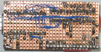
The two pictures below shows the completed interface. There is no significance in the differing wire sizes
I just used the first piece that came to hand.
In common with all subsequent pictures to get an enlarged
view 'click' on the image.

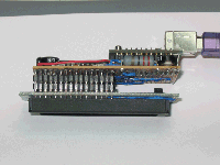
The next picture shows the modular connector strip pin and socket arrangement used to join the display unit to the interface module.
Note that in this prototype there is no other way to physically secure this connection and thus it is
therefore possible to place undue strain on the connection, usually resulting in the copper strip lifting away
from the board. It is strongly recommended that some sort of support be introduced, possibly using threaded rod and nuts and washers, or perhaps some type of
threaded pillar can be employed. Also note that the strip board is not quite as wide as the pcb used on
the display unit, this was due to an error on my part (I really should ensure that only one pencil mark
is made!). The two boards should be the same size to allow for securely fixing the strip board to the PCB.
Note that the strip board sizes shown in the parts list reflect the size of the 16 by 2 line LCD that was
used. If a 4 line by 20 character display is used then the strip board should be be tha same size as the
pcb on the LCD display, once again to allow for a secure fix between the LCD and the interface.
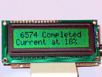
The picture below shows the finished project displaying my SETI statistics.
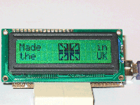
The next image shows the default bootstrap display - please note that I retain the copyright for the project.
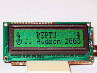
The picture below shows a user defined bootstrap screen that I have created in order to show what can be done. Users can redefine the eight user defined characters and create their own display. More details of how this can be achieved are provided in the PC software section.
